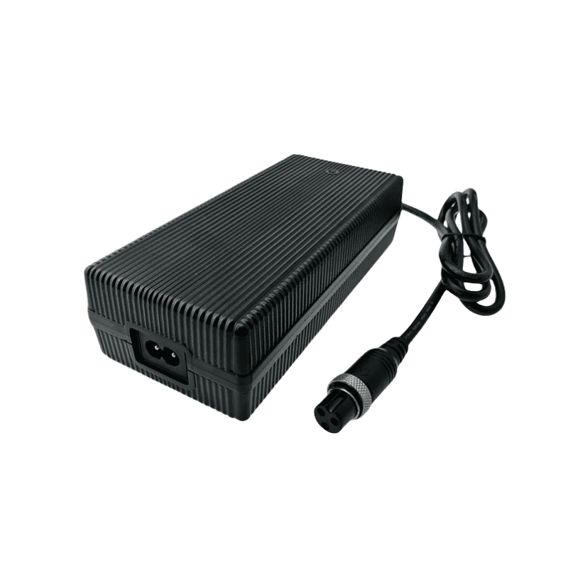
25.2V 7A Li-ion Charger for 6S 22.2V Battery
Engineered for high-capacity industrial drone fleets, standard AGVs, and heavy-duty portable backup power banks, the Phonix® FX2527000 (25.2V 7A) delivers a continuous 176.4W output to safely compress fleet charging cycles. Utilizing a heavy-mass 178X80X64mm sealed chassis, this high-amperage module drops charging times without employing failure-prone cooling fans, eliminating the noise and internal contamination risks common in harsh maintenance depots. Managed by a dedicated MCU running a dynamic three-stage charge algorithm, it actively controls terminal current to prevent grid-side stress while maximizing cell service life.
Description
Optimizing Magnetic Flux Margins and Heavy-Copper Trace Geometry for 170W+ Output Blocks
Pushing a continuous 7A current loop into a 6S lithium assembly within a sealed, fanless 178X80X64mm chassis requires careful control over internal copper and core losses. The Phonix® FX2527000 directly addresses this by integrating a high-permeability power transformer engineered with a large magnetic saturation margin, ensuring stable inductance even under full 180W maximum output saturation. To prevent excessive localized heating from the high current, the internal multi-layer PCB features extra-thick, heavy-copper traces that lower the overall trace impedance on the secondary side. This design choice limits parasitic voltage drops and ensures precise Constant Voltage (CV) cross-checking directly at the main connector pins. Because the 800g structural enclosure dispenses with open air vents, it acts as a permanent barrier against conductive metallic dust, carbon particles, and dynamic factory humidity. This eliminates the path-tracking and component value drift that often shorten the lifespan of standard vented chargers, maintaining a clean case temperature rise well under < 40°C.
Technical Parameters
| Category | Technical Parameter | Engineering Specification | Remarks / Test Conditions |
|---|---|---|---|
| 1. Input Specs | Rating Input Voltage | 100-240 Vac | 50/60 Hz Universal Main Grid Global Adaptation |
| Input Voltage Range | 90-264 Vac | Uninterrupted output regulation through severe local line sags | |
| Rating Input Current | 1.0 A / RMS | @ 100V AC Input, Full Load (Optimized Operational Window) | |
| Max Input Power | 208.0 W | Calculated primary baseline under peak continuous loading limits | |
| 2. Output Specs | No Load Output Voltage | DC 25.2 V | Precision voltage reference window; total pack overcharge prevention |
| Output Voltage Range | DC 21.20-25.2 V | Dynamic closed-loop regulation tracking architecture | |
| Charging Current | 7 A ±10% | Constant Current (CC) fast bulk injection phase | |
| Charging Voltage | DC 25.2 V ±0.2 V | Constant Voltage (CV) saturation safety tracking boundary | |
| Pre-charge Current | 0.7 A ±0.1 A | Automated low-voltage cell activation loop active when pack ≤ 18V | |
| Charge-end Current | ≤ 1.4 A ±10% | Strict 20% cutoff setting to suppress internal cell polarization | |
| Suitable Battery Type | 6S Li-ion / Li-Po Core Configurations | Calibrated component matching for 22.2V nominal packs | |
| Max Output Power | 180.0 W | Continuous operational output power envelope rating (25.2V X 7A) | |
| Ripple Voltage | ≤ 168 mV | Full load, Peak-to-Peak (Vp-p noise smoothing filtering) | |
| Efficiency (Natural Convection) | ≥ 85.0% | Full load @ 220V AC inside fully enclosed fanless hardware assembly | |
| Efficiency (Forced Air Cooling) | ≥ 90.0% | Audited performance under integration with external forced airflow design | |
| 3. Protection & Indicators | Short-Circuit / Reversed Protection | Yes / Yes | Instant microsecond solid-state isolation cutoff and latching lockout |
| Power LED State | Red | Primary AC mainline input verified active | |
| Charging LED (No Battery) | All Off | Open-circuit standby verification status loop | |
| Charging LED (Active Charge) | Flashing One by One | Active sequential capacity tracking output indication | |
| Charging LED (Finished) | All On / Green On | 100% saturation reached; automated standby safety lock engaged | |
| Charging LED (Error State) | All Flashing | Fault status latch active (Over-temperature, output short, reverse connections) | |
| 4. Environmental | Operating Temperature | -10 to +40 °C | Continuous operation under full thermal stability saturation points |
| Storage Temperature | -40 to +70 °C | Protects component structural integrity across long-range shipping transit | |
| Operating / Storage Humidity | < 90% RH / 0-95% RH | Non-condensing atmospheric evaluation limits | |
| Cooling Mechanics | Natural Convection | Zero mechanical noise; zero moving part wear vectors | |
| Vibration Resistance | 5 MM / 50 HZ / 600 S | Meets non-operating equipment transit shock thresholds | |
| Impact Resistance | 1-meter drop test, 3 times | Chassis structural impact retention verified | |
| 5. Mechanical | Net Weight | 800 g | Ruggedized, heavy-duty industrial chassis mass |
| Dimensions | 178X80X64 mm | Heavy industrial configuration built for high continuous output stability | |
| Output Connector | Refer to Order Guide | Custom terminal options tailored to specific enterprise hardware arrays | |
| 6. Safety & Reliability | Max Temperature Rise | < 40 °C on casing | Tested under maximum continuous load saturation metrics |
| Safety Approvals | CE, TUV, FCC, PSE, CCC | Direct global shipping compliance authentication | |
| MTBF | 50,000 Hours | Calculated component lifecycle stress profiles | |
| ESD Immunity | 8.0 KV | Electrostatic arc safety separation line | |
| Dielectric Leakage Threshold | ≤ 0.25 mA | Audited leakage parameters under peak operating stress | |
| Hi-Pot Insulation | i/p to o/p: 3000V (1 min) | Galvanic primary to secondary safety barrier isolation |
Industrial Grid Scaling & Customized Fleet Deployments
The integrated sequential LED panel offers direct capacity status data for production supervisors managing multi-bay fulfillment racks or large charging benches. For major distribution depots or high-rate ground automation stations requiring extreme fast-charging grid installations, procurement leads can cross-reference our heavy-power 25.2V 10A industrial charger schematics. Phonix® provides complete modular configuration for enterprise OEM/ODM programs, letting engineering leads assign specific heavy output terminations—including high-amperage Anderson power blocks, locking 3-pin XLR housings, or thick copper alligator clamps certified to align with global TUV safety engineering specifications.
Reviews
There are no reviews yet.