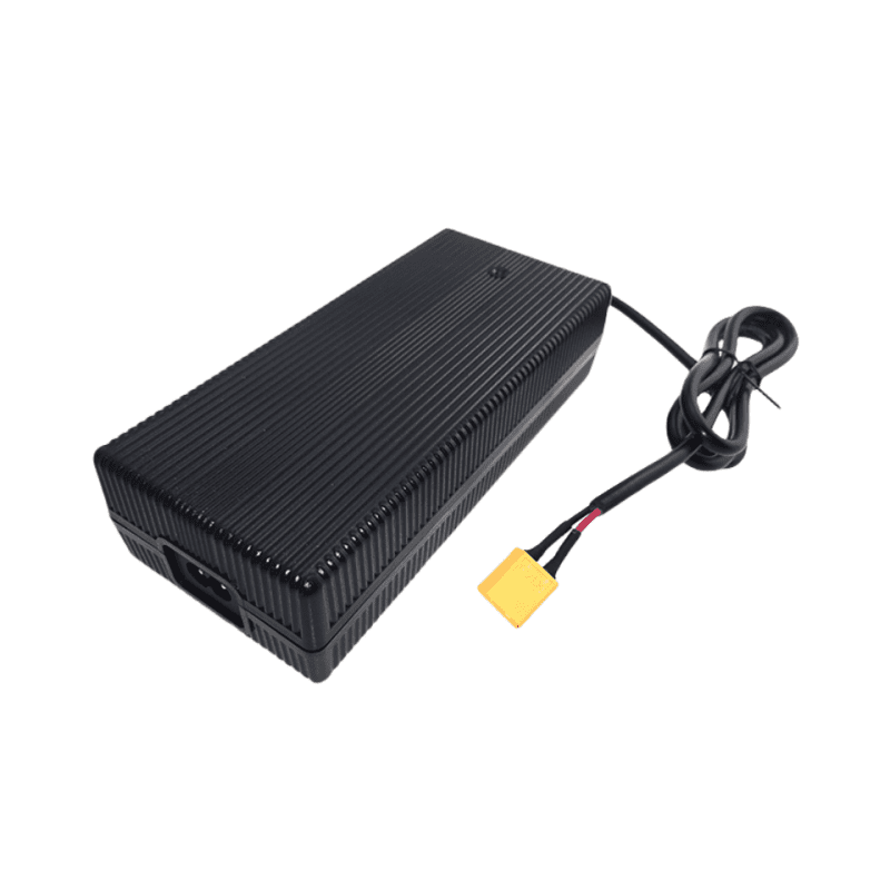
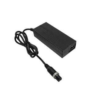
21V 9A Li-ion Battery Charger for 5S 18.5V Battery
To eliminate system latency and protect high-capacity asset readiness within intensive multi-shift warehouse networks, heavy industrial plant facilities, and automated delivery fleets, the Phonix® FX2109000 introduces an unyielding 189W continuous output pathway as a premium 21V 9A Li-ion battery charger. Developed to neutralize localized cell impedance and combat dynamic electrochemical polarization across 5S 18.5V Lithium-ion and Li-Po battery packs, this infrastructure-grade station ensures strict terminal tracking precision under dense operating duty cycles. The fully sealed, fanless housing completely isolates sensitive logic pathways from abrasive workshop dust, fine processing soot, and atmospheric humidity spikes within a unified 178X80X46 mm framework. Achieving an audited full-load energy efficiency of >= 88.5% under pure convection cooling—and scales up to >= 93.0% when integrated into systems utilizing forced-air ventilation—the internal layout uses an interleaved active power factor correction matrix to safeguard local sub-panels against voltage sags. Supervised by an independent hardware microcontroller, the module triggers immediate solid-state latching isolation cuts against over-voltage spikes, output shorts, and reverse line contacts. Engineered for zero-maintenance integration backed by a validated 50,000-hour MTBF and our 5-year factory warranty, this 9A fast-charging asset secures peak fleet availability while lowering the enterprise total cost of ownership (TCO).
Description
Sustained Harmonic Distortion Suppression via Interleaved Active PFC Matrix
Injecting a continuous 189W high-current fast-charge curve into heavy tool configurations or centralized battery banks demands highly sophisticated control over input line structures to insulate facility distribution grids from severe phase disruptions. The Phonix® FX2109000 utilizes an integrated interleaved active power factor correction topology cooperating with optimized LLC resonant secondary systems to guarantee high utility grid parity. Contained in a flame-retardant solid polymer enclosure measuring 178X80X46 mm and weighing 850g, the system removes open mechanical cooling fan structures in favor of pure natural air convection cooling. Barring open airflow pathways preserves internal multi-layer PCB layouts from conductive carbon scale, airborne fibers, and moisture tracking bridges that induce premature component value drift. This sealed architecture maintains maximum casing thermal rise under < 40°C during persistent constant-current bulk charge phases, insulating inner switching pathways and maximizing hardware deployment lifecycles。
Technical Parameters
| Category | Technical Parameter | Engineering Specification | Remarks / Test Conditions |
|---|---|---|---|
| 1. Input Specs | Rating Input Voltage | 100-240 Vac | 50/60 Hz Universal Utility Grid Compliance |
| Input Voltage Range | 90-264 Vac | Maintains steady output charging curves through severe line sags | |
| Rating Input Current | 2.14 A / RMS | @ 100V AC Input, Full Load (Calibrated with Active PFC Matrix) | |
| Power Factor (PF) | >= 0.98 | Mandatory Active PFC for commercial grid distribution optimization | |
| Max Input Power | 213.6 W | Calculated closed-loop baseline: Pout (189W) / Efficiency (88.5%) | |
| 2. Output Specs | No Load Output Voltage | DC 21.0 V | Precision voltage reference window; coordinates absolute overcharge mitigation |
| Output Voltage Range | DC 18.50-21.0 V | Dynamic closed-loop saturation curve tracking regulation | |
| Charging Current | 9 A ±10% | High-rate Constant Current (CC) fast-charge bulk injection phase | |
| Charging Voltage | DC 21.0 V ±0.2 V | Constant Voltage (CV) saturation curve parameter tracking | |
| Pre-charge Current | 0.9 A ±0.1 A | Automated cell safety activation initiates when pack voltage ≤ 15V | |
| Charge-end Current | ≤ 0.9 A ±10% | Strict 10% cutoff rule to counter electrochemical polarization errors | |
| Suitable Battery Type | 5S Li-ion / Li-Po Battery Networks | Calibrated hardware matching for 18.5V nominal enterprise arrays | |
| Timer Protection | — | Autonomous internal hardware phase runtime monitoring | |
| Max Output Power | 189 W | Continuous continuous output power envelope (21V X 9A) | |
| Ripple Voltage | ≤ 168 mV | Full load, Peak-to-Peak (Vp-p high-frequency filter suppression) | |
| Efficiency (Natural Convection) | ≥ 88.5% | Full load @ 220V AC under completely enclosed fanless conditions | |
| Efficiency (Forced Air Cooling) | ≥ 93.0% | Tested with external 20 CFM system integration airflow management | |
| 3. Protection & Indicators | Short-Circuit / Reversed Protection | Yes / Yes | Instant microsecond solid-state isolation cutoff and latching lockout |
| Power LED State | Red | Primary AC mainline input verified active | |
| Charging LED (No Battery) | All Off | Open-circuit standby verification status loop | |
| Charging LED (Active Charge) | Flashing One by One | Active sequential capacity charging tracking indication | |
| Charging LED (Finished) | All On / Green On | 100% saturation reached; automated standby safety lock engaged | |
| Charging LED (Error State) | All Flashing | Fault status latch active (Over-temperature, line short, reverse connections) | |
| 4. Environmental | Operating Temperature | -10 to +40 °C | Sustained operation under full thermal stability saturation points |
| Storage Temperature | -40 to +70 °C | Protects component structural integration across long-range shipping transit | |
| Operating / Storage Humidity | < 90% RH / 0-95% RH | Non-condensing atmospheric evaluation limits | |
| Cooling Mechanics | Natural Convection | Zero mechanical noise; zero moving part wear vectors | |
| Vibration Resistance | 5 MM / 50 HZ / 600 S | Meets non-operating equipment transit shock thresholds | |
| Impact Resistance | 1-meter drop test, 3 times | Chassis structural impact retention verified | |
| 5. Mechanical | Net Weight | 850 g | Total mass of reinforced infrastructure assembly |
| Dimensions | 178X80X46 mm | Compact multi-layer mechanical space-saving layout | |
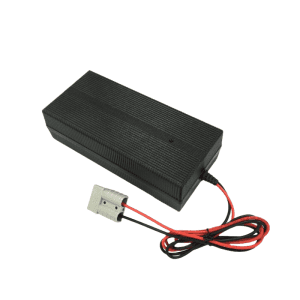
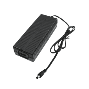
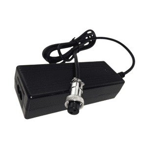
| Output Connector | Refer to Order Guide | Custom terminal options tailored to specific enterprise hardware systems | |
| 6. Safety & Reliability | Max Temperature Rise | < 40 °C on casing | Tested under maximum continuous load saturation metrics |
| Safety Approvals | CE, TUV, FCC, PSE, CCC | Direct global shipping compliance authentication | |
| MTBF | 50,000 Hours | Calculated component lifecycle stress profiles | |
| ESD Immunity | 8.0 KV | Electrostatic arc safety separation line | |
| Dielectric Leakage Threshold | ≤ 0.25 mA | Audited leakage parameters under peak operating stress | |
| Hi-Pot Insulation | i/p to o/p: 3000 V (1 min) | Galvanic primary to secondary safety barrier isolation |
Fleet Infrastructure Control & Specialized Terminal Interfacing
The integrated sequential LED capacity network offers immediate status monitoring for equipment managers tracking multi-bay distribution arrays on high-volume factory floors. For specialized industrial configurations requiring reduced fast-charge delivery to support compact tool clusters or manage local branch panel thresholds, project planners can review our high-efficiency 21V 8A Li-ion battery charger parameter blueprints. Phonix® supports comprehensive OEM/ODM structural adaptations, enabling procurement officers to configure high-durability output interfaces, including multi-point aviation couplers, solid coaxial systems, heavy-duty insulated clamps, or high-amp Anderson connections certified under international UL infrastructure engineering safety codes.
Reviews
There are no reviews yet.