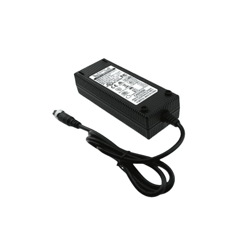
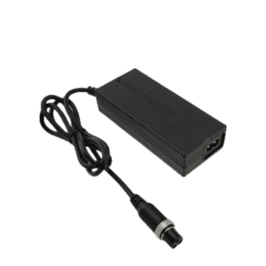
25.2V 4A Li-ion Charger for 6S 22.2V Battery
Phonix® FX2524000 is an infrastructure-grade 25.2V 4A (100.8W) smart fast charger optimized for 6S 22.2V Li-ion/Li-Po industrial battery packs. Engineering a full 100W+ baseline into a portable 154X60X36mm fanless chassis, it bars airborne workshop contamination while maintaining ≥85.0% full-load efficiency via static natural convection. Governed by a dedicated hardware MCU loop executing strict multi-stage charging tracking, a certified 50,000-hour MTBF, and our 5-year factory warranty, this silent power module secures maximum equipment readiness for heavy-duty drone bays, material handling electronics, and rugged field instruments.
Description
Optimizing Transformer Core Flux and Soft-Switching Duty Cycles for 100W+ Platforms
Scaling continuous energy pathways to a 100.8W baseline within a slim 154X60X36mm polymer footprint requires careful control over high-frequency magnetic design. The Phonix® FX2524000 manages this through an advanced ferrite core transformer with an optimized flux density rating, successfully preventing magnetic core saturation even during peak constant-current bulk loading. Operating alongside zero-voltage switching (ZVS) timing circuits, the hardware limits secondary thermal spiking right at the primary switching mosfet junction. By relying entirely on high-conductivity internal thermal pads instead of failure-prone mechanical fans, the unit operates with absolute mechanical silence. This fully sealed structural layout creates a solid climate barrier, blocking fine workshop carbon dust, humid atmospheric tracking layers, and abrasive micro-particles from compromising sensitive internal feedback loops, maintaining a strict case temperature rise under < 40°C.
Technical Parameters
| Category | Technical Parameter | Engineering Specification | Remarks / Test Conditions |
|---|---|---|---|
| 1. Input Specs | Rating Input Voltage | 100-240 Vac | 50/60 Hz Universal Utility Grid Worldwide Deployment |
| Input Voltage Range | 90-264 Vac | Maintains uninterrupted output regulation through severe local line sags | |
| Rating Input Current | 1.0 A / RMS | @ 100V AC Input, Full Load (Optimized Input Primary Baseline) | |
| Max Input Power | 125.0 W | Calculated baseline under full continuous thermal saturation | |
| 2. Output Specs | No Load Output Voltage | DC 25.2 V | Precision voltage reference window; eliminates battery cell overcharge |
| Output Voltage Range | DC 21.20-25.2 V | Dynamic closed-loop saturation tracking regulation curve | |
| Charging Current | 4 A ±10% | Constant Current (CC) high-rate bulk current injection phase | |
| Charging Voltage | DC 25.2 V ±0.2 V | Constant Voltage (CV) saturation management safety boundary | |
| Pre-charge Current | 0.4 A ±0.1 A | Automated safe cell reactivation active when pack voltage ≤ 18V | |
| Charge-end Current | ≤ 0.8 A ±10% | Strict 20% cutoff setting to suppress internal cell polarization | |
| Suitable Battery Type | 6S Li-ion / Li-Po Battery Core Formations | Calibrated component matching for 22.2V nominal industrial packs | |
| Max Output Power | 100.8 W | Continuous continuous output power envelope (25.2V X 4A) | |
| Ripple Voltage | ≤ 168 mV | Full load, Peak-to-Peak (Vp-p high-frequency noise smoothing) | |
| Efficiency (Natural Convection) | ≥ 85.0% | Full load @ 220V AC under completely enclosed fanless conditions | |
| Efficiency (Forced Air Cooling) | ≥ 90.0% | Tested with auxiliary integration forced airflow management | |
| 3. Protection & Indicators | Short-Circuit / Reversed Protection | Yes / Yes | Instant microsecond solid-state isolation cutoff and latching lockout |
| Power LED State | Red | Primary AC mainline input verified active | |
| Charging LED (No Battery) | All Off | Open-circuit standby verification status loop | |
| Charging LED (Active Charge) | Flashing One by One | Active sequential capacity tracking output indication | |
| Charging LED (Finished) | All On / Green On | 100% saturation reached; automated standby safety lock engaged | |
| Charging LED (Error State) | All Flashing | Fault status latch active (Over-temperature, output short, reverse connections) | |
| 4. Environmental | Operating Temperature | -10 to +40 °C | Sustained operation under full thermal stability saturation points |
| Storage Temperature | -40 to +70 °C | Protects component structural integration across long-range shipping transit | |
| Operating / Storage Humidity | < 90% RH / 0-95% RH | Non-condensing atmospheric evaluation limits | |
| Cooling Mechanics | Natural Convection | Zero mechanical noise; zero moving part wear vectors | |
| Vibration Resistance | 5 MM / 50 HZ / 600 S | Meets non-operating equipment transit shock thresholds | |
| Impact Resistance | 1-meter drop test, 3 times | Chassis structural impact retention verified | |
| 5. Mechanical | Net Weight | 450 g | Ruggedized, mid-tier mobile hardware package mass |
| Dimensions | 154X60X36 mm | Optimized mid-power packaging layout for standalone or bay installation | |
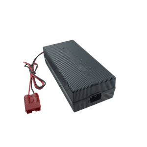
| Output Connector | Refer to Order Guide | Custom terminal options tailored to specific enterprise hardware arrays | |
| 6. Safety & Reliability | Max Temperature Rise | < 40 °C on casing | Tested under maximum continuous load saturation metrics |
| Safety Approvals | CE, TUV, FCC, PSE, CCC | Direct global shipping compliance authentication | |
| MTBF | 50,000 Hours | Calculated component lifecycle stress profiles | |
| ESD Immunity | 8.0 KV | Electrostatic arc safety separation line | |
| Dielectric Leakage Threshold | ≤ 0.25 mA | Audited leakage parameters under peak operating stress | |
| Hi-Pot Insulation | i/p to o/p: 3000 V (1 min) | Galvanic primary to secondary safety barrier isolation |
Mid-Power Charging Management & Hardware Interface Adaptability
The micro-controlled dual-color LED structure gives facility engineers clear tracking over asset states when managing automated warehouse fleets or decentralized ground terminals. For heavy infrastructure installations requiring high-current fast-charging pathways to maximize fleet rotation speeds, procurement supervisors can reference our heavy-duty 25.2V 10A Li-ion battery charger blueprints. Phonix® fully supports custom OEM/ODM modifications, allowing hardware leads to order specific output configurations, including heavy insulated copper clamps, secure GX aviation connectors, durable coaxial pins, or high-amp Anderson systems certified to align with strict global PSE regulatory compliance standards.


Reviews
There are no reviews yet.