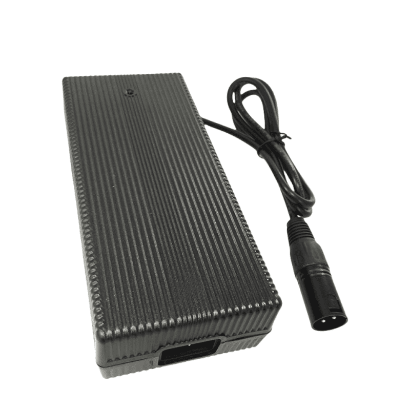
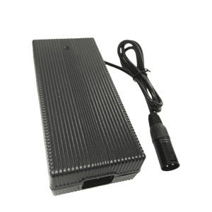
21V 8A Li-ion Battery Charger for 5S 18.5V Battery
To accelerate equipment turnaround times and support continuous grid operations within heavy-duty industrial automation hubs, heavy logistics plants, and material handling systems, the Phonix® FX2108000 provides a high-capacity 168W continuous energy flow as a premium 21V 8A Li-ion battery charger. Developed specifically to regulate charging stresses and mitigate dynamic electrochemical polarization across 5S 18.5V Lithium-ion and Li-Po battery modules, this ruggedized station maintains terminal tracking accuracy under persistent workshop conditions. The fully sealed, fanless housing isolates the internal switching paths from abrasive dust, metallic particles, and ambient moisture inside a standardized 178X80X46 mm envelope. Operating at an audited full-load conversion efficiency of >= 88.5% to restrict structural thermal loading, the hardware leverages an interleaved active power factor correction matrix to shield local branch panels from line sags. Overseen by an independent microcontroller, the unit initiates hardware-level latching cuts against over-voltage anomalies, output shorts, and reverse line connections. Backed by a verified 100,000-hour MTBF and an authoritative 5-year factory warranty, this 8A fast-charging solution reduces total cost of ownership (TCO) while securing uncompromised equipment availability.
Description
Industrial Power Factor Compliance via Interleaved Active PFC Topology
Deploying a continuous 168W fast-charging platform into dense commercial assembly lines or industrial charging racks mandates strict regulation of input current wave shapes to protect building sub-panels from harmonic distortions. The Phonix® FX2108000 integrates an interleaved active power factor correction circuit working alongside optimized LLC resonant converter topologies to preserve high distribution grid purity. Housed in a flame-retardant solid polymer chassis measuring 178X80X46 mm and weighing 850g, the unit rejects mechanical cooling fan structures in favor of pure natural air convection. Eliminating open-air airflow channels bars entry to conductive carbon residues, metallic particles, and humid tracking paths that trigger early component value drift or internal layer shorts. This closed-chassis architecture limits maximum case temperature rise to under < 40°C during maximum constant-current bulk charge phases, shielding internal multilayer PCB paths and reinforcing fleet operational uptime.
Technical Parameters
| Category | Technical Parameter | Engineering Specification | Remarks / Test Conditions |
|---|---|---|---|
| 1. Input Specs | Rating Input Voltage | 100-240 Vac | 50/60 Hz Global Main Grid Universal Compliance |
| Input Voltage Range | 90-264 Vac | Maintains steady output power through severe line sags | |
| Rating Input Current | 1.94 A / RMS | @ 100V AC Input, Full Load (Audited with Mandatory Active PFC) | |
| Power Factor (PF) | >= 0.98 | Active PFC circuit matrix for professional distribution management | |
| Max Input Power | 189.8 W | Calculated closed-loop baseline: Pout (168W) / Efficiency (88.5%) | |
| 2. Output Specs | No Load Output Voltage | DC 21.0 V | Precision reference window; completely eliminates battery pack overcharging |
| Output Voltage Range | DC 18.50-21.0 V | Dynamic closed-loop saturation tracking regulation curve | |
| Charging Current | 8 A ±10% | High-rate Constant Current (CC) constant bulk injection phase | |
| Charging Voltage | DC 21.0 V ±0.2 V | Constant Voltage (CV) saturation management curve | |
| Pre-charge Current | 0.8 A ±0.1 A | Automated safe cell reactivation active when loop voltage ≤ 15V | |
| Charge-end Current | ≤ 0.8 A ±10% | Strict 10% cutoff rule to suppress electrochemical cell polarization | |
| Suitable Battery Type | 5S Li-ion / Li-Po Battery Assemblies | Calibrated parameter matching for 18.5V nominal enterprise arrays | |
| Timer Protection | — | Autonomous internal hardware phase runtime limiter | |
| Max Output Power | 168 W | Continuous continuous output power envelope (21V X 8A) | |
| Ripple Voltage | ≤ 168 mV | Full load, Peak-to-Peak (Vp-p high-frequency smoothing filtering) | |
| Efficiency | ≥ 88.5% | Full load @ 220V AC with active Middle-High power stage optimization | |
| 3. Protection & Indicators | Short-Circuit / Reversed Protection | Yes / Yes | Instant microsecond solid-state isolation cutoff and latching lockout |
| Power LED State | Red | Primary AC mainline input verified active | |
| Charging LED (No Battery) | All Off | Open-circuit standby verification status | |
| Charging LED (Active Charge) | Flashing One by One | Active sequential capacity tracking output indication | |
| Charging LED (Finished) | All On / Green On | 100% cell saturation reached; automated standby safety lock engaged | |
| Charging LED (Error State) | All Flashing | Fault loop latch active (Over-temperature, line short, reverse connections) | |
| 4. Environmental | Operating Temperature | -10 to +40 °C | Sustained operation under full thermal stability saturation points |
| Storage Temperature | -40 to +70 °C | Protects component structural integration across long-range shipping transit | |
| Operating / Storage Humidity | < 90% RH / 0-95% RH | Non-condensing atmospheric evaluation limits | |
| Cooling Mechanics | Natural Convection | Zero mechanical noise; zero moving part wear vectors | |
| Vibration Resistance | 5 MM / 50 HZ / 600 S | Meets non-operating equipment transit shock thresholds | |
| Impact Resistance | 1-meter drop test, 3 times | Chassis structural impact retention verified | |
| 5. Mechanical | Net Weight | 850 g | Total mass of reinforced infrastructure assembly |
| Dimensions | 178X80X46 mm | Robust, industrial-grade heavy-duty mechanical footprint layout | |
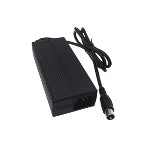
| Output Connector | Refer to Order Guide | Custom terminal options tailored to specific enterprise hardware systems | |
| 6. Safety & Reliability | Max Temperature Rise | < 40 °C on casing | Tested under maximum continuous load saturation metrics |
| Safety Approvals | CE, TUV, FCC, PSE, CCC | Direct global shipping compliance authentication | |
| MTBF | 100,000 Hours | Calculated component lifecycle stress profiles | |
| ESD Immunity | 8.0 KV | Electrostatic arc safety separation line | |
| Dielectric Leakage Threshold | ≤ 0.25 mA | Audited leakage parameters under peak operating stress | |
| Hi-Pot Insulation | i/p to o/p: 3000 V (1 min) | Galvanic primary to secondary safety barrier isolation |
Central Supply Management & Hardware Interface Adaptability
The diagnostic sequential LED capacity structure provides real-time oversight for asset management crews directing multi-tier storage docks on active plant floors. For setups where lower current injection rates are designated to optimize smaller equipment groups or satisfy targeted distribution lines, engineering planners can reference our compatible 21V 7A Li-ion battery charger specification indices. Phonix® fully accommodates tailored OEM/ODM requests, enabling procurement supervisors to select specialized high-durability output termination hardware including heavy insulated clamps, multi-point aviation plugs, solid coaxial systems, or quick-disconnect Anderson couplers certified to align with global TUV safety engineering specifications.
Reviews
There are no reviews yet.