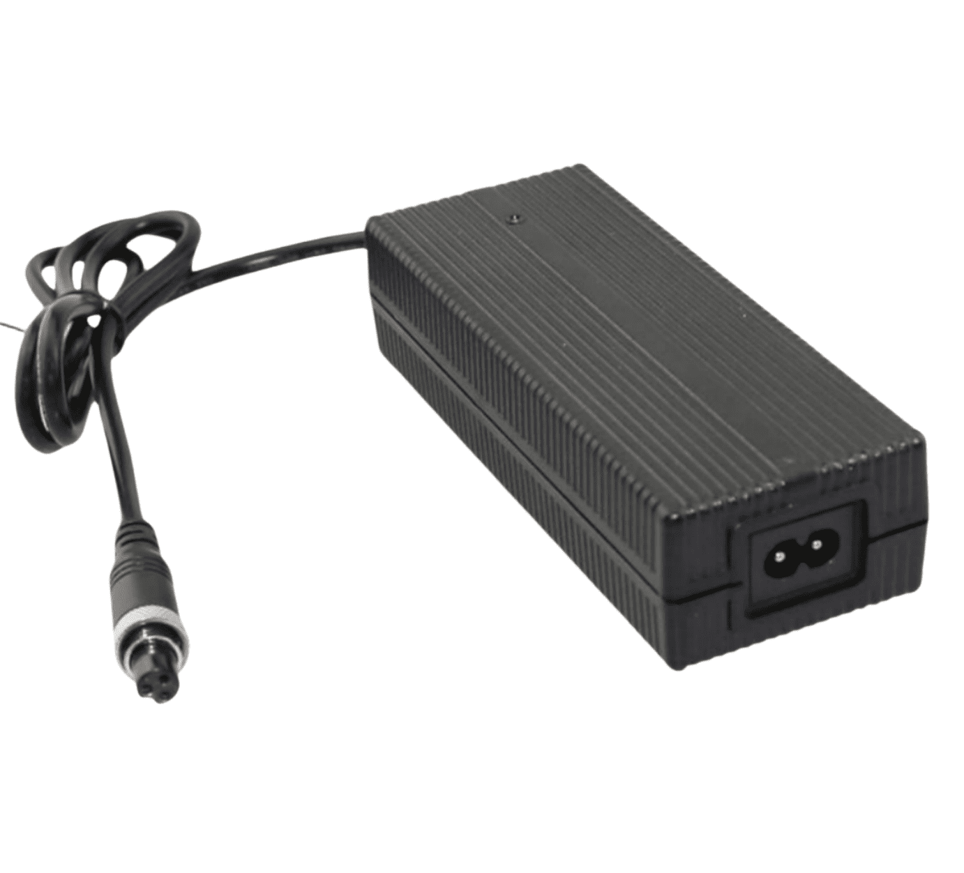
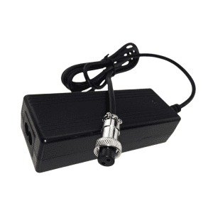
21V 6A Li-ion Battery Charger for 5S 18.5V Battery
To preserve maximum manufacturing asset readiness and eliminate systemic charging bottlenecks within centralized maintenance depots, critical aerospace test grounds, and high-frequency production lines, the Phonix® FX2106000 serves as a heavy-duty 126W high-capacity 21V 6A Li-ion battery charger. Meticulously engineered to prevent advanced cell imbalance and eliminate electrochemical degradation across 5S 18.5V Lithium-ion and Li-Po battery modules, this infrastructure-grade power supply maintains an unyielding voltage profile under peak loads. The fanless, tightly sealed chassis completely isolates inner switching circuitry from fine airborne metallic dust, processing debris, and warehouse condensation inside a standard 154X60X36 mm footprint. Achieving an elevated full-load conversion efficiency of >= 91.0% to attenuate thermal load buildup, the system utilizes a high-speed tracking microcontroller to govern microsecond hardware-level latching cuts against over-voltage spikes, output short-circuits, and reverse-polarity line contacts. Built for prolonged industrial life cycle integration backed by a validated 100,000-hour MTBF and an authoritative 5-year factory warranty, this 6A charging platform ensures stable power delivery without risking localized electrical grid instabilities.
Description
Grid-Compliant Power Factors via Interleaved Active PFC Topology
Deploying high-current 126W charging platforms onto crowded plant sub-panels requires strict regulation of harmonic distortion to prevent total power quality degradation or crosstalk with sensitive industrial automation lines. The Phonix® FX2106000 integrates an interleaved active power factor correction topology working alongside synchronous rectification secondary topologies to enforce optimal electrical phase alignment. Encased in a fully sealed, flame-retardant solid polymer enclosure measuring 154X60X36 mm and weighing 450g, the hardware cooling relies entirely on natural air convection. Eliminating open mechanical cooling fans bars the intake of conductive factory soot, abrasive composite particulates, and atmospheric humidity vectors that routinely degrade standard electronics. The design bounds the maximum chassis thermal rise below 40°C during persistent constant-current phases, protecting multilayer PCB paths and lowering the overall equipment lifecycle cost for enterprise operations.
Technical Parameters
| Category | Technical Parameter | Engineering Specification | Remarks / Test Conditions |
|---|---|---|---|
| 1. Input Specs | Rating Input Voltage | 100-240 Vac | 50/60 Hz Universal Utility Grid Compliance |
| Input Voltage Range | 90-264 Vac | Maintains full-rated charging output through localized line sags | |
| Rating Input Current | 1.41 A / RMS | @ 100V AC Input, Full Load (Calibrated with Active PFC) | |
| Power Factor (PF) | >= 0.98 | Mandatory Active PFC for commercial grid optimization | |
| Max Input Power | 138.5 W | Calculated closed-loop baseline: Pout (126W) / Efficiency (91.0%) | |
| 2. Output Specs | No Load Output Voltage | DC 21.0 V | Precision voltage reference window; completely limits overcharging risks |
| Output Voltage Range | DC 18.50-21.0 V | Dynamic closed-loop saturation curve tracking | |
| Charging Current | 6 A ±10% | High-rate Constant Current (CC) fast-charge bulk injection phase | |
| Charging Voltage | DC 21.0 V ±0.2 V | Constant Voltage (CV) saturation curve management | |
| Pre-charge Current | 0.6 A ±0.1 A | Triggers automatically when cell voltage drops ≤ 15V | |
| Charge-end Current | ≤ 0.6 A ±10% | Strict 10% cutoff threshold to eliminate electrochemical polarization | |
| Suitable Battery Type | 5S Li-ion / Li-Po Battery Networks | Calibrated parameter matching for 18.5V nominal cell arrays | |
| Timer Protection | — | Autonomous internal hardware phase runtime monitoring | |
| Max Output Power | 126 W | Continuous output power envelope (21V X 6A) | |
| Ripple Voltage | ≤ 168 mV | Full load, Peak-to-Peak (Vp-p high-frequency attenuation filtering) | |
| Efficiency | ≤ 91.0% | Full load @ 220V AC with verified Synchronous Rectification | |
| 3. Protection & Indicators | Short-Circuit / Reversed Protection | Yes / Yes | Instant microsecond solid-state isolation cutoff and latching lockout |
| Power LED State | Red | Primary AC mainline input verified active | |
| Charging LED (No Battery) | All Off | Open-circuit standby verification loop status | |
| Charging LED (Active Charge) | Flashing One by One | Active sequential capacity tracking output indication | |
| Charging LED (Finished) | All On / Green On | 100% saturation reached; automated standby safety lock engaged | |
| Charging LED (Error State) | All Flashing | Fault status latch active (Over-temperature, line short, reverse connections) | |
| 4. Environmental | Operating Temperature | -10 to +40 °C | Sustained operation under full thermal stability saturation points |
| Storage Temperature | -40 to +70 °C | Protects component structural integration across long-range shipping transit | |
| Operating / Storage Humidity | < 90% RH / 0-95% RH | Non-condensing atmospheric evaluation limits | |
| Cooling Mechanics | Natural Convection | Zero mechanical noise; zero moving part wear vectors | |
| Vibration Resistance | 5 MM / 50 HZ / 600 S | Meets non-operating equipment transit shock thresholds | |
| Impact Resistance | 1-meter drop test, 3 times | Chassis structural impact retention verified | |
| 5. Mechanical | Net Weight | 450 g | Total mass of reinforced infrastructure assembly |
| Dimensions | 154X60X36 mm | Compact multi-layer mechanical space-saving layout | |
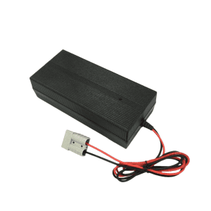
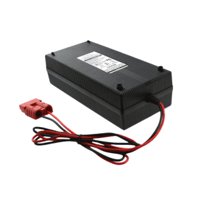
| Output Connector | Refer to Order Guide | Custom terminal options tailored to specific enterprise hardware systems | |
| 6. Safety & Reliability | Max Temperature Rise | < 40 °C on casing | Tested under maximum continuous load saturation metrics |
| Safety Approvals | CE, TUV, FCC, PSE, CCC | Direct global shipping compliance authentication | |
| MTBF | 100,000 Hours | Calculated component lifecycle stress profiles | |
| ESD Immunity | 8.0 KV | Electrostatic arc safety separation line | |
| Dielectric Leakage Threshold | ≤ 0.25 mA | Audited leakage parameters under peak operating stress | |
| Hi-Pot Insulation | i/p to o/p: 3000 V (1 min) | Galvanic primary to secondary safety barrier isolation |
Central Charging Grid Management & Enterprise Infrastructure Scaling
The integrated sequential LED capacity matrix offers instant status visibility for facility crews tracking multi-tier charging arrays on active warehouse floors. For automation environments requiring lower-rate charging options to support lighter mobile electronic hardware or maintain total branch current targets, engineering supervisors can cross-reference our stable 21V 5A Li-ion battery charger specification data. Phonix® provides complete OEM/ODM customization services, enabling procurement managers to configure specialized high-durability output interfaces such as industrial coaxial pins, heavy-duty insulated clamps, multi-point aviation couplers, or quick-disconnect Anderson components certified to meet international UL safety compliance codes.

Reviews
There are no reviews yet.