Energy density keeps rising, charge currents keep climbing, thermal margins keep shrinking, and every new battery platform demands more data and more coordination.
In this environment, a charger stopped being a “power accessory” years ago.
It has become the system component that shapes safety, cycle life, charging speed, and field reliability.
Many teams still struggle with a key decision:
stick with a single MCU, or move to a dual-MCU architecture?
The performance gap between these two choices is no longer theoretical.
In real projects, it shows up as yield rate, field failures, EMI stability, OTA reliability, and even customer trust.
1. The Linear Era: When “delivering current” was the entire job
Older chargers were essentially analog blocks:
- Iron transformer
- Rectifier
- Large thermal mass
- Fixed output behavior
They were tolerant, predictable, and extremely slow.
For modern lithium packs, they operate like a blind pump: power goes out, and that’s the end of the story.
Nothing about the battery’s condition participates in the process.
For power tools, e-mobility, or ESS, this is long past its limit.
2. SMPS became standard, but the control logic stayed shallow
Switch-mode power supplies solved efficiency and size.
They allowed CC/CV and basic sensor inputs.
But they still lacked something essential:
situational awareness.
No interpretation of pack behavior, no algorithm decisions, no adaptive corrections, no communication workload planning.
You get power conversion, not a charging strategy.
3. The single-MCU phase brought basic intelligence—but also exposed hard limits
Once 8-bit and 32-bit controllers became cheap, the charger finally gained a brain:
- Pre-charge
- CC/CV stages
- Basic sampling
- Temperature cutoffs
- Elementary state machines
Good enough for slow charging and simple packs.
But as soon as the industry pushed the boundaries, the design began to show its structural weaknesses.
Control tasks and computation fighting for CPU time
Sampling jitter shows up the moment peripheral load increases.
Higher charge rates amplify the instability.
Communication stacks block the real-time loop
BLE, Wi-Fi, CAN, or cloud logging compete for the same CPU cycles that drive PWM and protection.
Fast charging magnifies every timing inconsistency
At 1C or higher, even small timing drift becomes visible on the output waveform.
Anyone maintaining a high-power charger has seen these symptoms more than once.
4. Dual-MCU designs (STM32 for control + ESP32 for communication) fix the root cause, not the symptoms
The value is not “more hardware”.
It’s job separation.
STM32 handles the electrical world
- PWM
- High-speed ADC
- Protection in microseconds
- Tight control loops
- Stable state management
ESP32 handles the digital world
- Wi-Fi / BLE
- OTA
- App communication
- Cloud reporting
- Log handling
- BMS protocol adaptation
Linked by UART or CAN, the boundary is clean.
Both subsystems stay predictable.
This separation addresses the exact pain points engineering teams see during validation and field operation.
5. Where the real-world value shows up
Stable control at high charge rates
The control loop runs undisturbed, even when communication traffic spikes.
Sampling consistency directly improves thermal behavior and cycle life.
Actual project example:
A 6-A tool charger cut its CC ripple from ±150 mA to ±30 mA simply by moving BLE off the main MCU.
Higher safety margin
If the communication side crashes, the control side keeps enforcing voltage/current limits.
Independent watchdogs keep the system recoverable.
Value for procurement:
Lower RMA rate, fewer catastrophic failures, and predictable field behavior.
More headroom for real algorithms
With the control MCU free from overhead, teams can add:
- Dynamic thermal derating
- Adaptive PID
- Voltage overshoot suppression
- Fast-sampling filters
- Charge-pattern learning
These directly affect charge time and pack longevity—things end users actually notice.
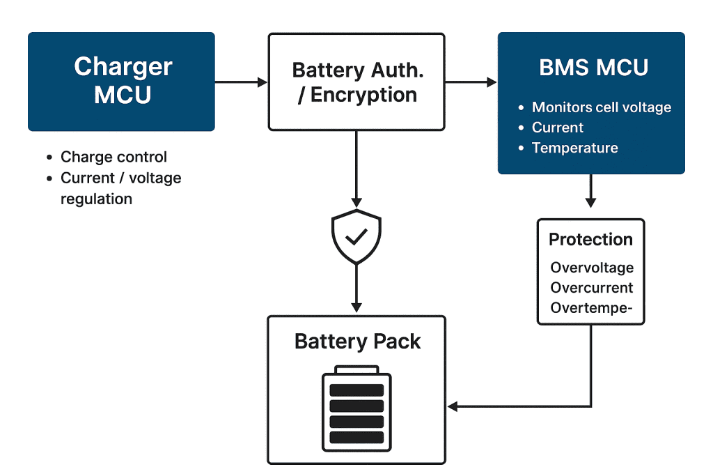
Better cooperation with BMS systems
Modern BMS protocols vary widely.
Running multiple protocol layers plus app communications on a single MCU is where most single-MCU designs collapse.
Dual-MCU setups manage:
- BMS handshake
- Cloud sync
- App telemetry
- Internal control logic
All at once, without timing conflicts.
Example:
An e-bike platform shifted to dual-MCU because single-MCU units would miss BMS heartbeat packets under heavy OTA load.
6. Different industries are converging on the same architecture for different reasons
Power tools / garden tools
- Higher charge rates
- Smaller thermal envelope
- Platform-based batteries
- OTA requirement from major brands
E-mobility
- Mandatory app visibility
- Real-time pack monitoring
- BMS integration
- BLE + Wi-Fi coexistence
ESS / industrial systems
- Multi-pack cooperation
- Event logging
- Remote diagnostics
- Lifetime optimization
They all share one expectation:
control must stay stable, communication must scale.
Dual-MCU is exactly that boundary.
7. The architecture unlocks product-platform behavior
Once a charger can maintain:
- Stable control at high current
- Reliable communication
- OTA without interrupting regulation
- Continuous logging
- Clean interaction with BMS and cloud
It stops being a disposable accessory.
It becomes a long-life platform that can continue to evolve without redesigning hardware.
This is why many engineering teams treat the charger as part of the battery ecosystem, not an isolated box.
8. Where the architecture is heading
Industry momentum points toward:
- Higher charge C-rates
- BMS-aware control loops
- Predictive thermal modeling
- Cloud-based cycle-life monitoring
- OTA as a default requirement
- Control MCUs with even faster ADCs
- Communication MCUs acting as mini gateways
Dual-MCU isn’t a trend; it’s becoming the baseline for next-generation charging platforms.
Dual-MCU Designs Smart Charger by Phonix Technology for Power Tools smart charging with 100% safety and monitor battery